Ceiling fans with lights wiring requirements
Ceiling fans with lights wiring requirements depend on the condition of the existing circuit, available conductors, control method, ceiling box support, and correct identification of neutral, earth, and switched active pathways. These wiring requirements are not universal because every installation may differ in how power is supplied and controlled through a wall switch or a remote receiver, and how safely the ceiling box supports the combined load.
Wiring suitability is determined by how the existing circuit is configured, what conductors are present, and whether the control method separates or combines fan motor and light output functions. In many cases, the presence of a neutral, earth connection, and correctly routed switched active line influences whether a standard or receiver-based configuration is required. The ceiling fans with lights guide provides broader context for how these systems are structured and compared across different installation needs.
Safety is a core constraint in ceiling fans with lights wiring requirements because incorrect handling of live supply wiring, neutral return paths, or earth grounding can create functional and safety risks. The ceiling box must be properly rated and structurally secure, and wiring work should remain aligned with applicable safety limits and typically requires licensed electrical verification rather than assumptions based on wire appearance or prior fittings.
At a practical level, understanding wiring requirements means first mapping how the existing circuit delivers power, then confirming how conductors are assigned to fan motor and light output through either a wall switch or a remote receiver system. From there, the relationship between neutral, earth, and switched active conductors defines how control behavior is achieved without assuming that wire layout or colour alone indicates function.
Existing circuit and cable conditions before wiring a ceiling fan with light
Existing circuit and cable conditions before wiring a ceiling fan with light depend on whether supply, switching, cable condition, ceiling access, and compliant installation conditions support a safe assessment for further wiring planning. This determines if the ceiling fan with light can be considered potentially suitable, requires electrician verification, or is unsuitable for direct installation.
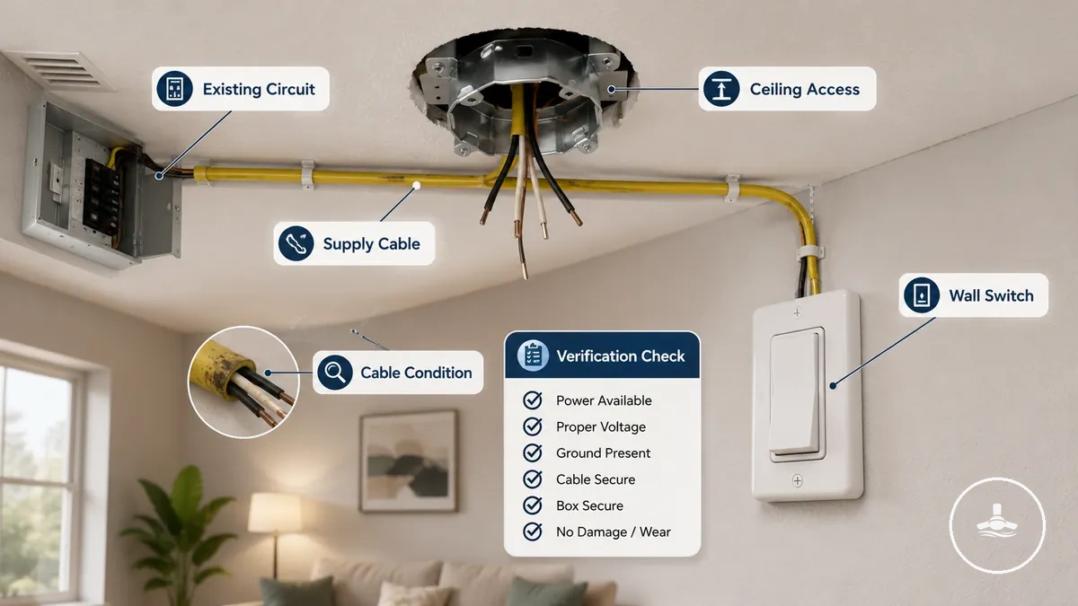
Readiness of the existing circuit is influenced by supply availability and how the wall switch is configured to control the installation point. The presence or absence of a switch leg or suitable branch circuit can change whether a ceiling fan with light can be supported without redesigning the control layout.
Cable condition and ceiling access define the physical limits of the installation environment. Older homes may show degraded insulation or limited conductor availability, while replacement installations may reuse existing wiring paths. Restricted ceiling access can limit inspection and make verification of the supply cable more complex, especially where hidden junctions exist.
Electrician verification is required when the existing circuit, cable condition, or switching layout cannot clearly support a compliant installation approach for a ceiling fan with light. In these cases, broader installation requirements may need to be reviewed through installation requirements before any wiring layout decisions are made.
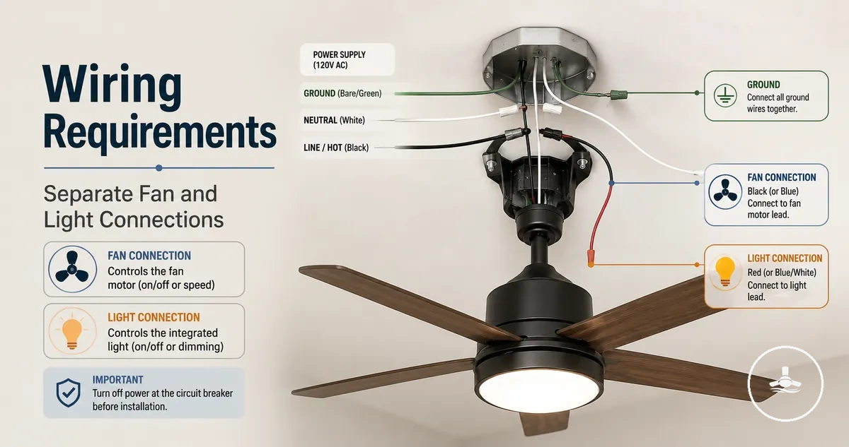
Wire colours and conductor roles in ceiling fan light wiring
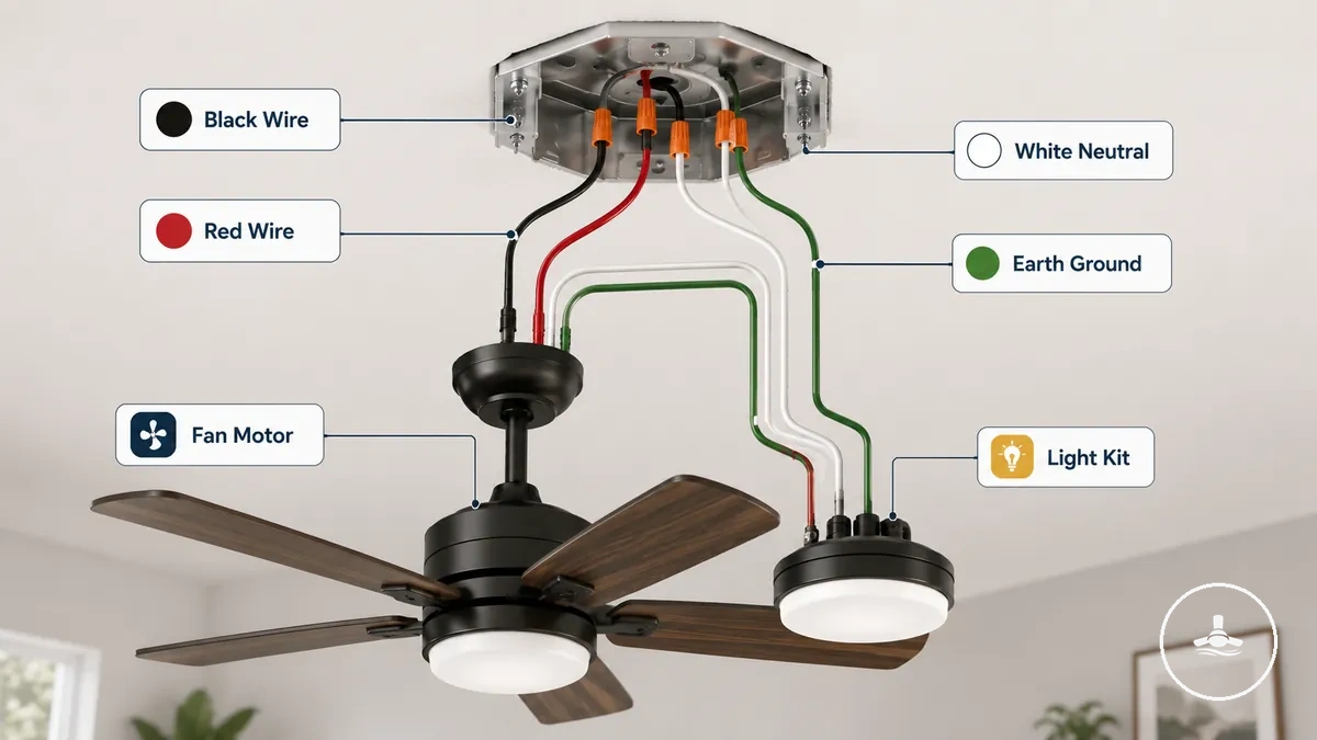
Wire colours and conductor roles in ceiling fan light wiring are clues to function rather than reliable proof of how a conductor is actually used, and confirmation is required before any interpretation is applied. In a ceiling fan with light setup, black wire, red wire, white wire, blue wire, and green wire may suggest possible roles, but actual function depends on verified testing at the installation point, creating a clear contrast between typical colour patterns and confirmed conductor role.
Conductor roles define how electricity is distributed within the system, including neutral return paths, earth grounding, switched active lines, and receiver-controlled outputs. These roles determine how the fan motor and light output respond to wall switch input or a remote receiver, regardless of how the wire is visually identified, so functional confirmation is always required.
To understand how wire colours relate to conductor roles, it helps to visualise the typical wiring layout and how each labelled conductor connects within a ceiling fan with light system. The diagram below shows common colour-role relationships used for reference only and not as direct wiring instruction.
The table below organizes common wire colours, their possible roles, required confirmation, and their effect on fan motor, light output, receiver, or wall switch control. This separates typical colour signals from the actual tested conductor function at the installation point.
| Wire colour or label | Common role signal | Must confirm before use | Wiring effect or risk |
|---|---|---|---|
| Black wire | Active / live / fan motor feed | Switched active verification required | May control fan motor operation via switch or receiver |
| Red wire | Switched active / light feed | Separate switching confirmation required | May control light output independently |
| White wire | Neutral return path | Neutral continuity must be confirmed | Enables return path for fan, light, or receiver |
| Blue wire | Light output / lamp wire | Fixture assignment must be confirmed | May control light kit function via receiver |
| Green wire / earth | Grounding conductor | Earth continuity must be confirmed | Supports grounding and fault protection |
Wire colours in ceiling fan light wiring vary by installation type, region, and product design, so colour patterns should only be treated as general signals. Only confirmed conductor roles determine actual function, especially when a receiver or wall switch changes how power is distributed to the fan motor and light output.
Black, red, white, and earth wires in fan and light connections
Black, red, white, and earth wires in fan and light connections represent common colour signals for conductor roles, but these signals are not a fixed rule and must be verified at each installation point. Colour conventions can vary by region, installation age, and product design, so interpretation should always stay conditional rather than assumed as direct instruction.
Colour variation means each wire should be treated as a potential indicator of function rather than a guaranteed role.
- Black wire — may relate to fan motor power or active feed; function can vary and requires confirmation of switching or control method.
- Red wire — may indicate a switched path for the light kit; role can differ depending on wall switch or receiver setup.
- White wire — typically associated with neutral return; must be confirmed as the return path for fan or light circuits.
- Earth wire — usually green or bare copper; provides protective ground for the fan motor and light kit, depending on installation design.
These colour-based signals should never replace verified conductor identification, since actual function depends on confirmed roles rather than visual wire colour alone in a ceiling fan with light connection system.
Unused or missing wires in common ceiling fan wiring setups
Unused wire, missing wire, and capped conductor conditions in ceiling box wiring often indicate incomplete or limited control layouts, especially where neutral, red wire, or receiver-related conductors are not clearly available. These conditions can limit how separate control is achieved and usually require electrician assessment before interpretation. Missing conductors can restrict control options in several ways:
- Unused wire — may indicate a spare conductor with unclear function in ceiling box wiring; requires electrician assessment to avoid incorrect interpretation.
- Missing wire — absence of a required conductor such as neutral can limit fan operation and reduce options for separate control.
- Capped conductor — often a capped red wire or unused switch leg; may indicate a deactivated path that no longer supports separate control.
- Absent neutral — in ceiling box wiring, a missing neutral can restrict receiver operation and shift dependency toward receiver-based configurations.
In practice, these conditions may result in combined control instead of separate control, or a shift toward receiver dependency when direct switching is limited. Because conductor function cannot be confirmed by appearance alone, electrician assessment remains necessary to determine safe and workable configuration options.
This chart shows the three main missing or unused wire conditions in ceiling fan wiring and explains their meanings, effects on separate control, and assessment requirements.

Control layouts that change how the fan and light are wired
Control layout determines how ceiling fan wiring requirements change between the supply, wall control, remote receiver, fan motor, and light output, meaning the wiring structure is dependent on the selected control method rather than a fixed conductor setup.
Control layout changes how the wiring relationship behaves across different configurations:
| Control layout | Wiring dependency | What changes | Main caution |
|---|---|---|---|
| Combined control | Single switched active from wall switch | Fan motor and light output operate together | Limits separate control options |
| Separate switches | Multiple switched active lines from wall switch | Fan motor and light output operate independently | May require additional conductors in ceiling box wiring |
| Remote receiver | Constant supply feeding remote receiver | Receiver distributes power to fan motor and light output | Depends on receiver and supply compatibility |
| Mixed control | Wall switch plus remote receiver | Combined control between wall switch and remote receiver | Compatibility depends on wiring configuration |
Combined control relies on a single wall switch and a single switched active, which typically links fan motor and light output together. Separate switch configurations depend on additional switched active conductors, which can increase ceiling box wiring requirements.
Remote receiver layouts shift control into the fan unit, where the remote receiver manages distribution of power to the fan motor and light output from a constant supply. Mixed control combines wall control input with a remote receiver, creating a hybrid setup where wiring and control dependencies must align.
When conductor availability or ceiling box wiring does not support the chosen control layout, professional assessment or rewiring may be required. For broader context on control options, see wall controls and smart controls, which explains how control methods influence wiring structure.
One wall switch for combined fan and light control
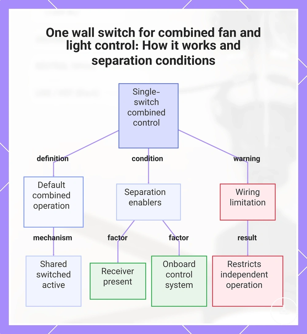
One wall switch for combined fan and light control means the fan motor and light usually operate together through a shared switched active, so both functions respond at the same time when the switch is used. In this setup, the single switch acts as the control point, and combined fan and light control is the default outcome unless an internal separation mechanism exists.
This combined operation is typically limited to unified control, but separation may still occur under specific conditions.
- Receiver present — may allow the fan motor and light to operate independently even when only one wall switch is installed.
- Onboard control system — can separate fan and light functions within the unit depending on internal design.
- Wiring limitation — absence of separate conductors can restrict independent operation from a single wall switch.
In most cases, one wall switch creates a shared switched active that links fan motor and light together, while separation depends on whether a receiver or onboard control is included and supported by the specific fan design and wiring configuration.
This chart explains how a single wall switch controls both fan and light together, and what conditions allow independent operation.
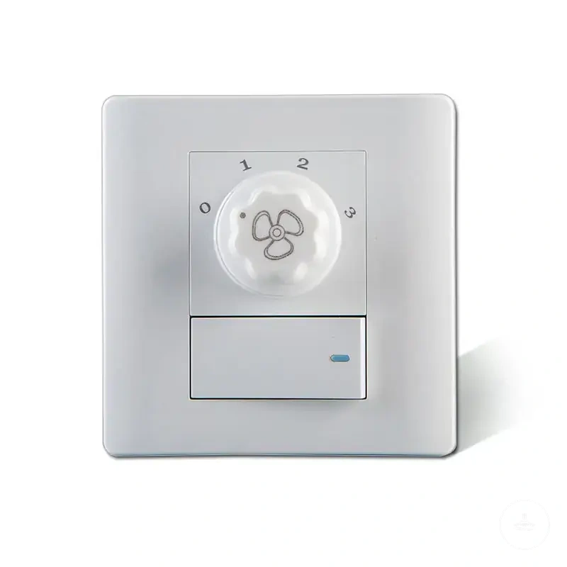
Separate wall switches for fan and light control
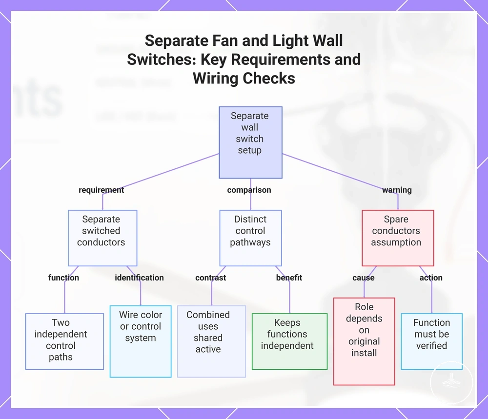
Separate wall switches for fan and light control depend on the availability of separate switched conductors, where a fan switch controls the fan motor and a light switch controls the light through independent paths. This setup enables separate operation because each function is driven by its own switched conductor, often identified through wiring signals such as a red wire for one circuit and a blue wire for the light, or through a compatible control system that supports independent outputs. Compared to combined switching, which uses a shared switched active, separate wall switches require distinct control pathways to keep fan switch and light switch functions independent.
Spare or unused conductors inside the ceiling box wiring cannot be assumed to support separate operation, since their role depends on how the circuit was originally installed and configured. Even when extra wires are present, their function must be verified because they may not correspond to usable switched conductors for either fan switch or light switch control. In many cases, correct identification and validation are required before any separate wall switches configuration can reliably support fan motor and light control without conflict.
This chart explains what separate wall switches for fan and light control need to work properly, including the requirement for separate switched conductors, a comparison with combined switching, and a warning about assuming spare conductors are usable.
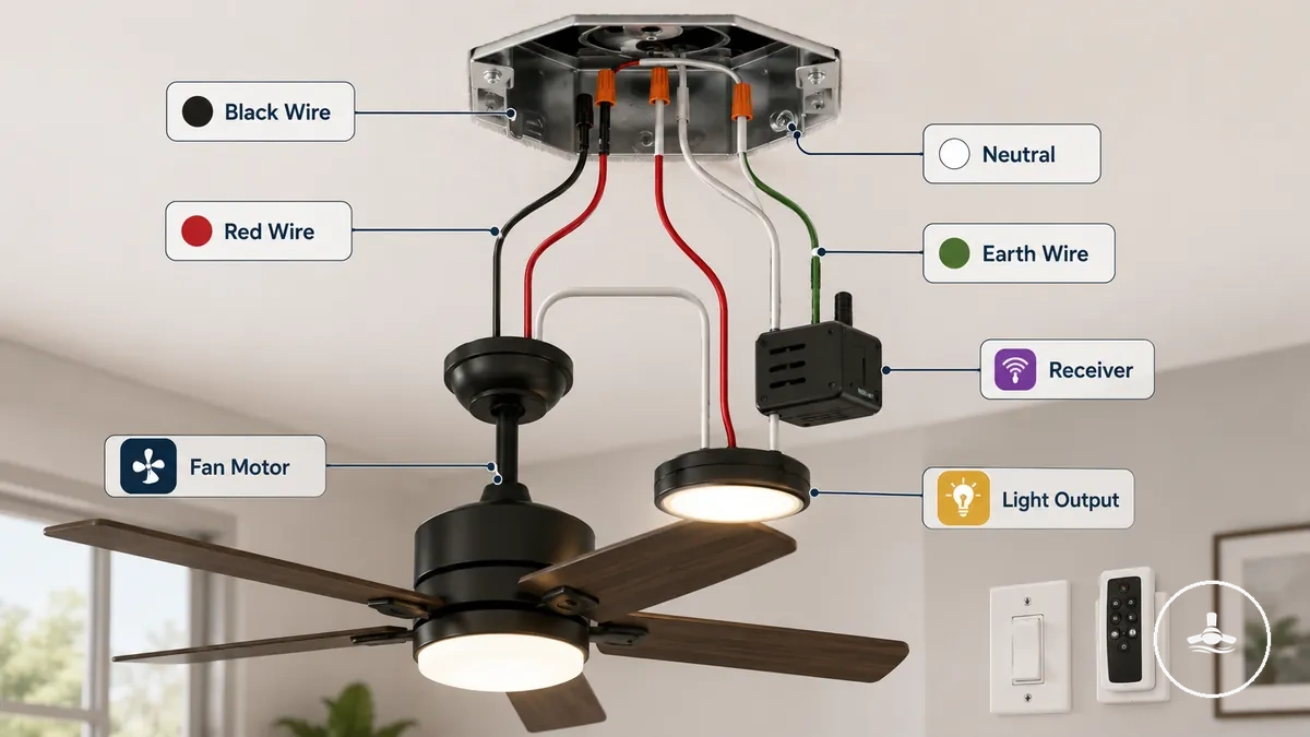
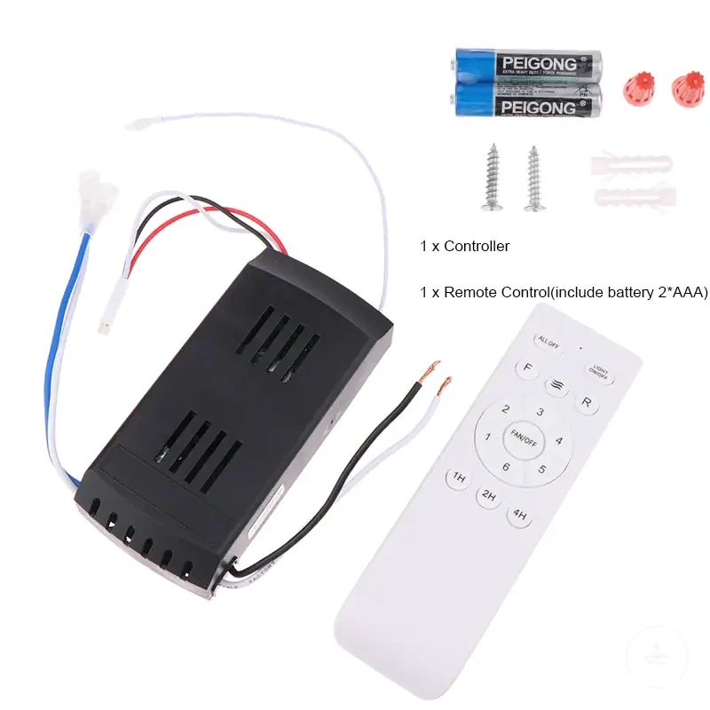
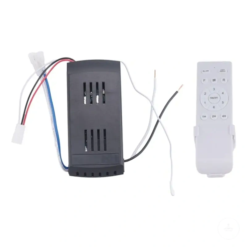
Remote receiver wiring between the supply, fan motor, and light
Remote receiver wiring between the supply, fan motor, and light refers to the way a remote receiver is positioned between the incoming supply and the outgoing fan motor and light output circuits. The remote receiver changes the control logic, but it does not remove the requirement for correct handling of supply, neutral, and earth connections within the overall wiring setup.
In this configuration, the remote receiver acts as an intermediate control module with an input terminal receiving power from the supply and output terminals distributing controlled power to the fan motor and light output. A simplified wiring path can be understood as: supply → remote receiver input terminal → remote receiver output terminal → fan motor / light output, while neutral and earth remain part of the supply-side connections for circuit reference and safety continuity. Exact terminal labeling and output separation can vary depending on the manufacturer diagram, so interpretation should always follow the provided manufacturer diagram rather than assumed layouts.
The behavior of motor speed control, light switching, and remote operation depends on how the remote receiver allocates its output terminals, but this allocation is not universal across all systems. Differences in receiver module design can affect how fan motor and light output are independently or jointly controlled, even when the supply conditions are correctly provided.
Remote and wall switch wiring in the same installation
Mixed control depends on whether the wall switch supplies switched power, acts as a wall controller, or only provides power to a compatible receiver, which determines how a remote receiver and wall switch share responsibility in the same installation. The interaction between wall switch, remote receiver, and fan functions is defined by control responsibility rather than a universal wiring pattern, with outcomes shaped by power isolation or overlapping control roles.
Decision mini-checklist:
- Wall switch provides switched power only to the remote receiver
- Wall controller function is compatible with the receiver control logic
- Remote receiver is present and coordinates fan motor and light output functions
- System allows power isolation without overlapping control commands
When remote receiver and wall switch coexist, outcomes depend on whether control is isolated or shared. A compatible receiver setup may support power isolation, where the wall switch only supplies switched power and the receiver manages fan motor and light output independently. In contrast, control conflict can occur when both the wall controller and receiver attempt to manage the same fan or light function, leading to overlapping commands that disrupt stable operation.
Connection points inside the ceiling box, canopy, receiver, and light kit
Connection points inside the ceiling fan system refer to the physical locations where the wiring relationship is distributed across the ceiling box, canopy, receiver, fan body, and light kit. These points define where electrical connection and structural integration occur, while each component contributes a specific role that may vary depending on the installation design and configuration.
A labelled overview helps organize where these connection points exist and how they relate to function and risk across the system.
| Location | Connection role | What to identify | Risk if misidentified |
|---|---|---|---|
| Ceiling box | Primary supply entry and structural support point | Supply cable entry and fixed mounting location | Confusion between structural support and electrical connection points |
| Canopy | Transition cover and wiring interface zone | Internal wiring path and connection space | Misreading as structural-only can obscure wiring relationship |
| Receiver | Control module for distributing fan and light functions | Input/output connection points for control distribution | Incorrect mapping may disrupt control allocation logic |
| Fan body | Motor housing and electrical output integration | Connection interface for fan motor supply | Misidentification may affect understanding of functional routing |
| Light kit | Light output assembly connection point | Electrical connection for illumination function | Incorrect mapping may separate intended light control function |
Structural mounting location and electrical connection location are related in physical space but are not the same function. The ceiling box or canopy may provide mounting support, while the actual wiring relationship occurs through designated electrical connection points within or between components.
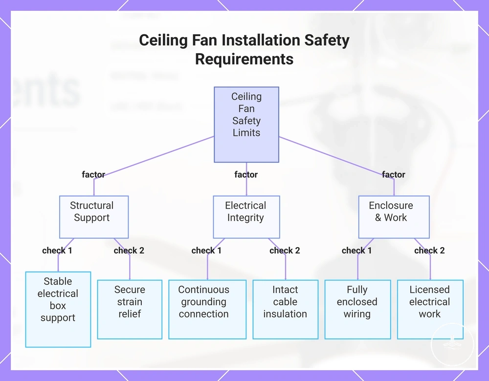
Electrical box support, grounding, and wiring safety limits
Electrical box support, grounding, and wiring safety limits depend on electrical box support, grounding, strain relief, cable condition, wiring enclosure, and licensed electrical work, which define whether a ceiling fan with light installation meets safety limits or requires further verification before any wiring relationship is considered suitable.
Safety limits are established through structural support, enclosure integrity, and cable protection before any installation assessment can proceed.
- Electrical box support — must provide stable structural support, as insufficient support can create movement risk and misalignment of the fan body.
- Strain relief — must secure incoming cables, as missing or weak strain relief can increase stress on conductors and contribute to overheating risk.
- Wiring enclosure — must fully contain and protect conductors, as exposed wiring can increase shock hazard and lead to inspection failure.
- Cable condition — must remain intact and undamaged, as degraded insulation can increase electrical fault risk and overheating conditions.
- Grounding — must maintain a continuous earth connection, as weak grounding can increase shock hazard during fault conditions.
- Licensed electrical work — must be applied where required, as unverified work can lead to non-compliant safety outcomes and failed inspections.
Electrical box support and earth connection integrity directly influence safety limits because structural instability can cause movement risk while grounding interruptions can increase shock hazard. Strain relief and cable condition also affect thermal stability inside the wiring enclosure by reducing stress points that may lead to overheating.
Before proceeding with any broader installation decision, the safety boundary should be reviewed through electrical safety checks, as electrical box support, grounding, and wiring enclosure conditions must remain within verified limits to reduce movement, shock hazard, and overheating risks.
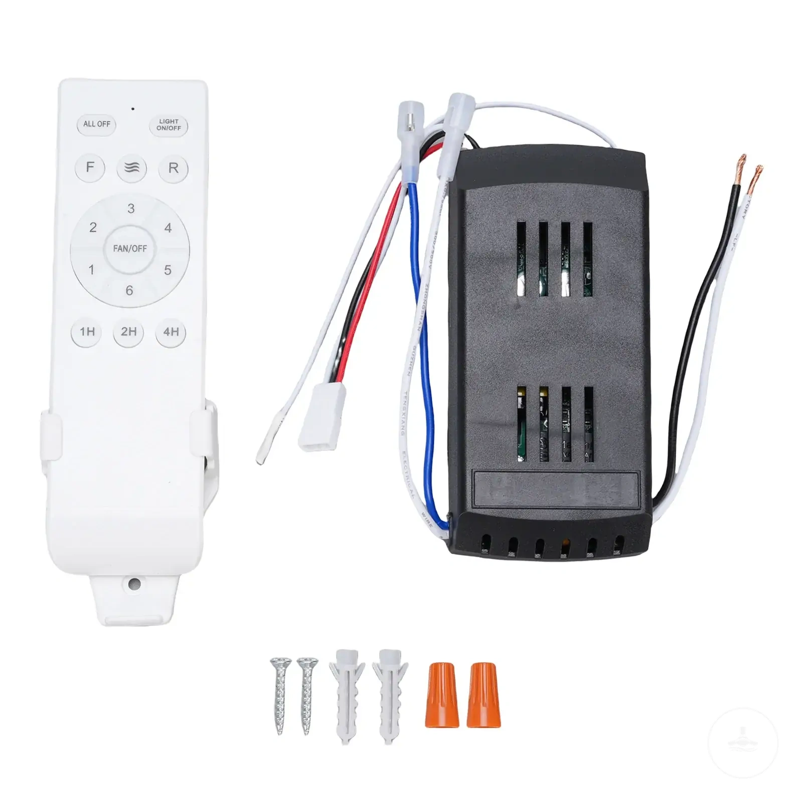
The products below are useful examples for comparing available options. Before buying, check that the compatibility criteria, key features, and product details match your needs.

This chart shows the key safety requirements and checks that define whether a ceiling fan installation meets electrical safety limits, covering structural support, electrical integrity, and enclosure verification.
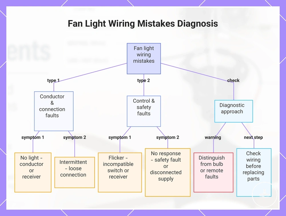
Wiring mistakes that can stop the fan light from working
Fan light not working is often linked to wiring mistakes such as incorrect conductor matching, receiver output issues, loose connections, incompatible switch configurations, or safety-related wiring faults, where the electrical path to the light circuit is interrupted or incorrectly routed rather than the light kit itself being failed.
Each symptom should be matched to a likely wiring condition before assuming a failed component, because wiring mistakes and control mismatches can produce overlapping outcomes across the fan light system.
- No light | incorrect conductor matching or receiver output issue | may indicate the light feed is not reaching the light kit due to wiring allocation or control path failure.
- Intermittent operation | loose connection in wiring enclosure or terminal points | may suggest unstable contact causing intermittent electrical continuity.
- Flicker | incompatible switch or unstable receiver output | may indicate fluctuating control signal or load mismatch in the circuit.
- No response | safety fault or disconnected supply path | may suggest upstream wiring interruption affecting the light circuit.
Receiver output issues and incompatible switch types can also contribute to wiring-related failures, where the control system does not properly align with the expected light circuit path, resulting in no light or unstable operation depending on the configuration.
Wiring mistakes should be separated from bulb failure, remote settings, dimmer incompatibility, or internal component faults, since these can produce similar symptoms without being directly related to conductor matching or connection integrity.
When diagnosing a ceiling fan light not working, it is important to distinguish wiring-related faults from broader system issues, especially when flickering ceiling fan light appears intermittently across different control modes or switch states.
This chart maps common fan light symptoms to their likely wiring causes and emphasizes the need to rule out other faults before replacing components.